Lily58 Pro
This Guide will help you build your Lily58 Pro kit.

0 - What you need
- Solder Iron
- Solder wire
- Soldering skills
- A computer in order to flash the firmware (MacOS, Windows, Linux)
- Switches 58x
- Keycaps
- Microcontroller 2x (if not added to cart during checkout)
- TRRS Cable
- USB-C Cable
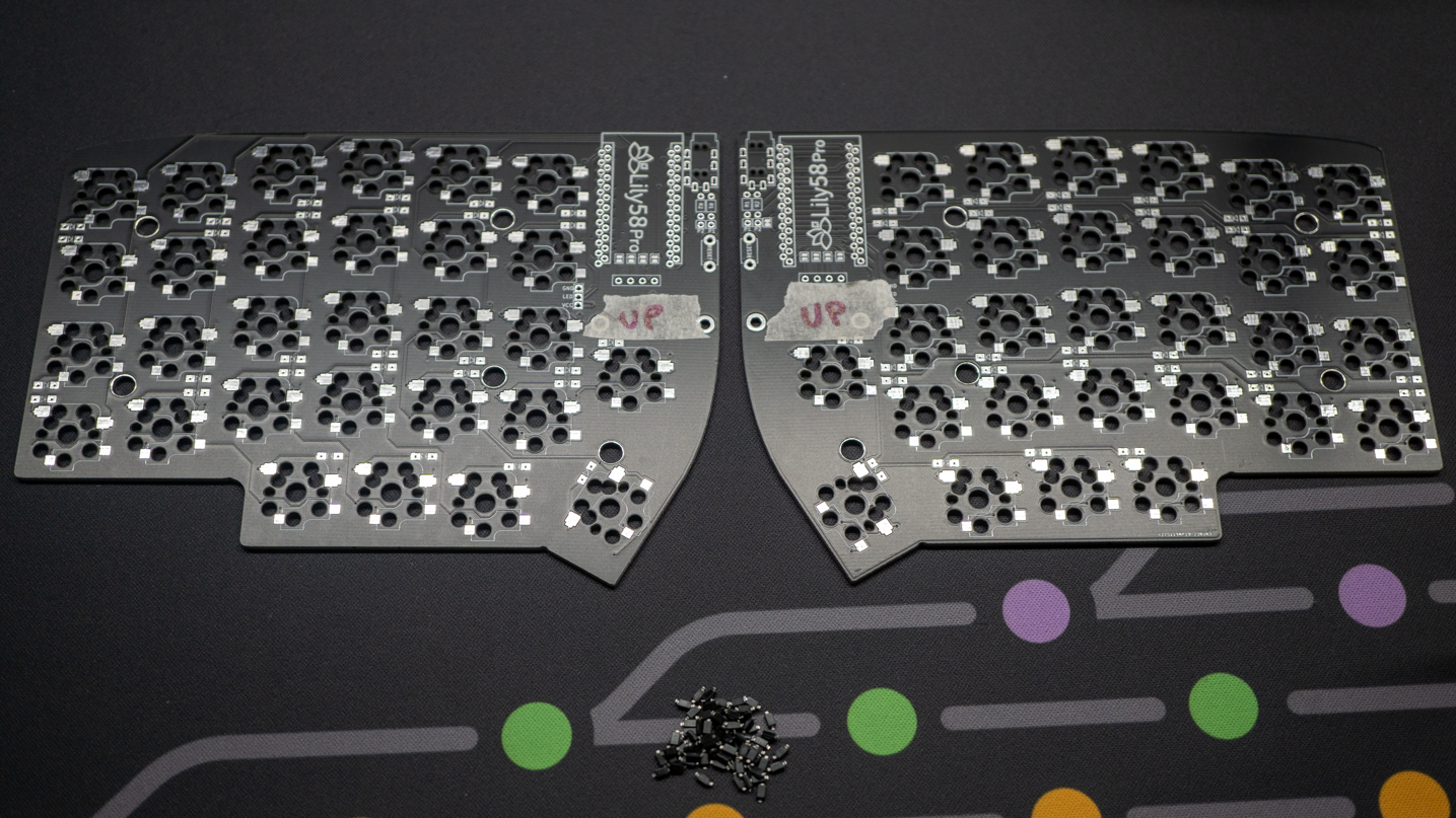
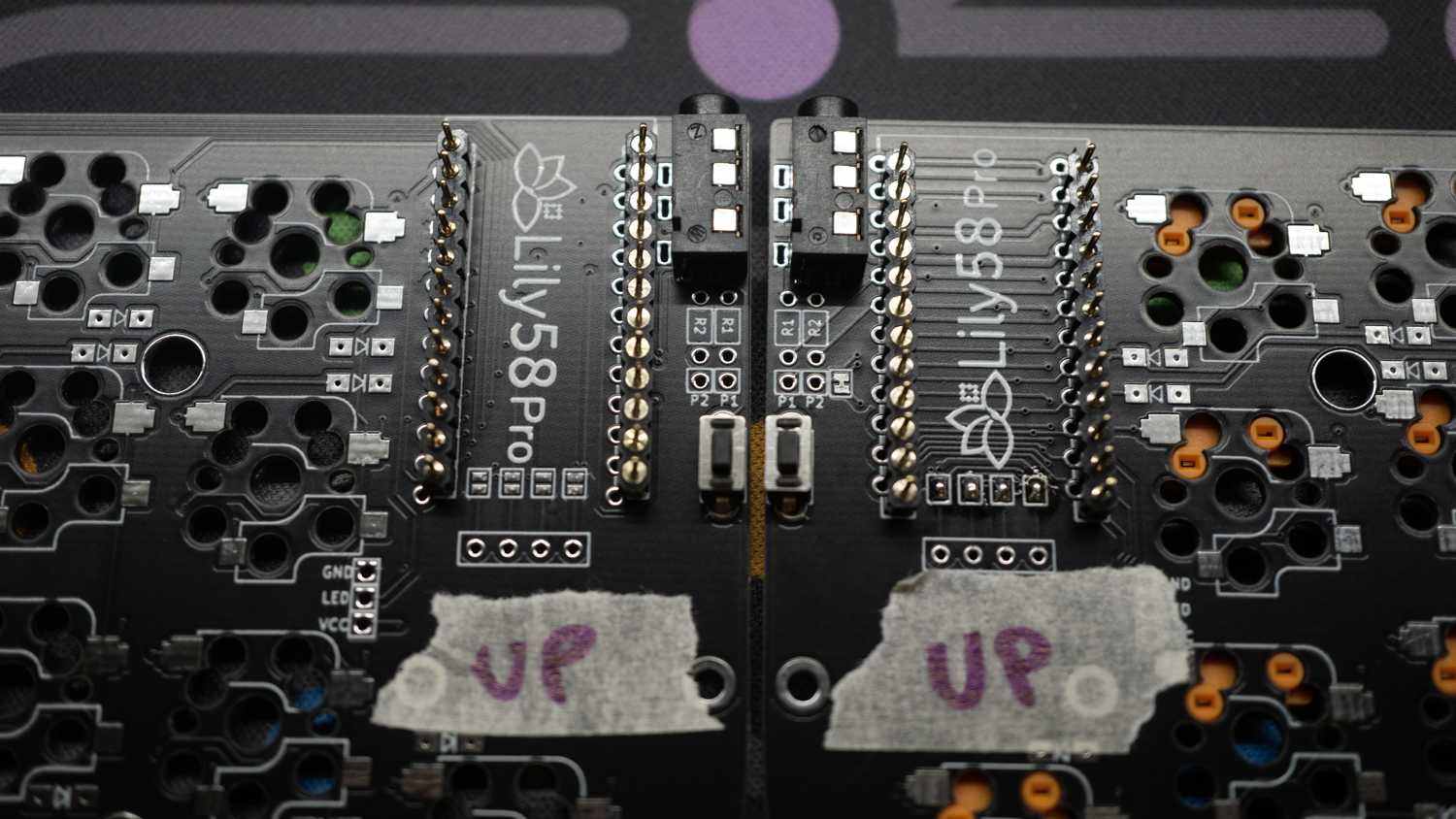
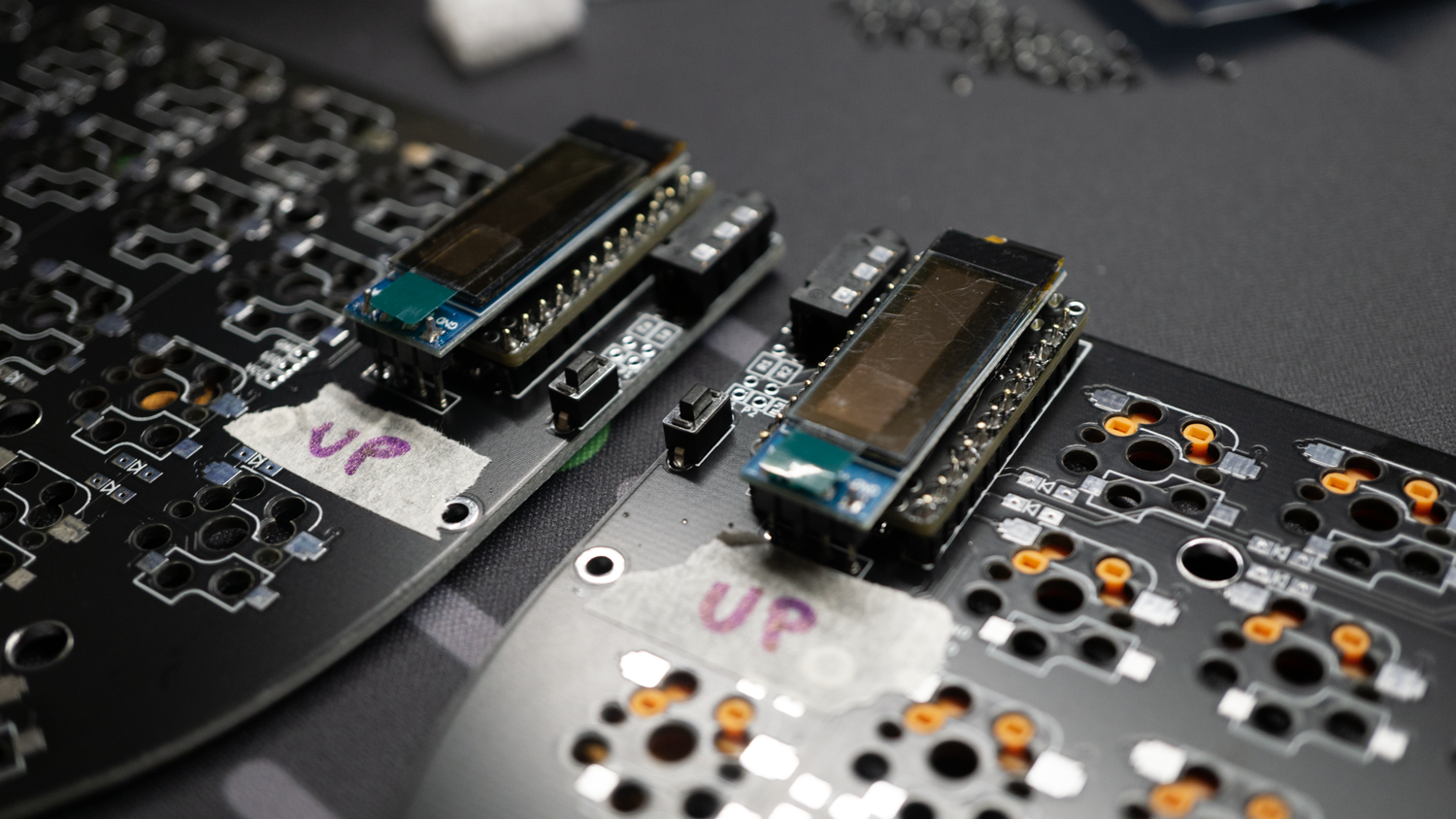
1 - Mark the up side of your PCBs
Put your two main PCBs in a mirrored way, attach a piece of tape and mark the UP side of both PCBs
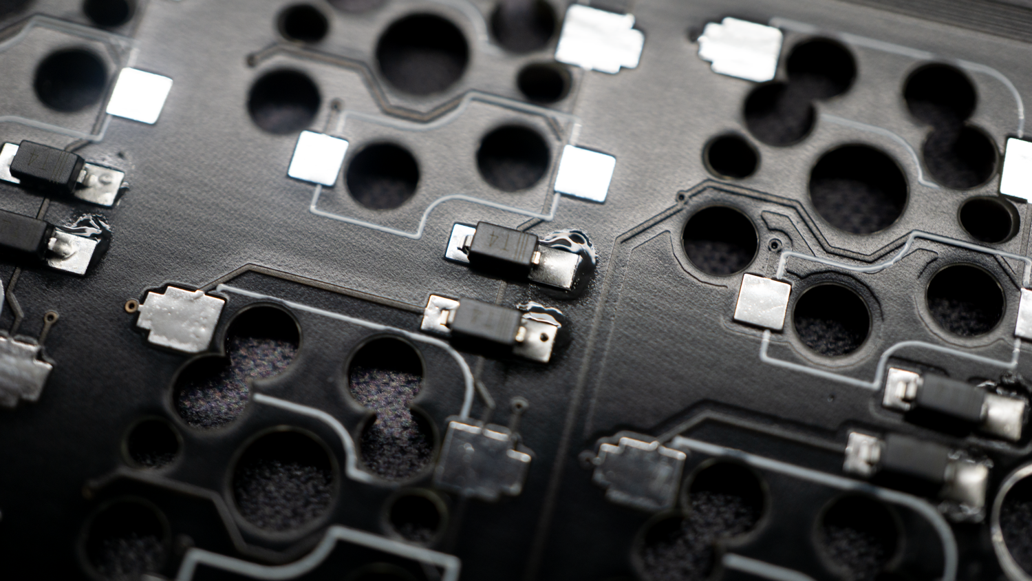
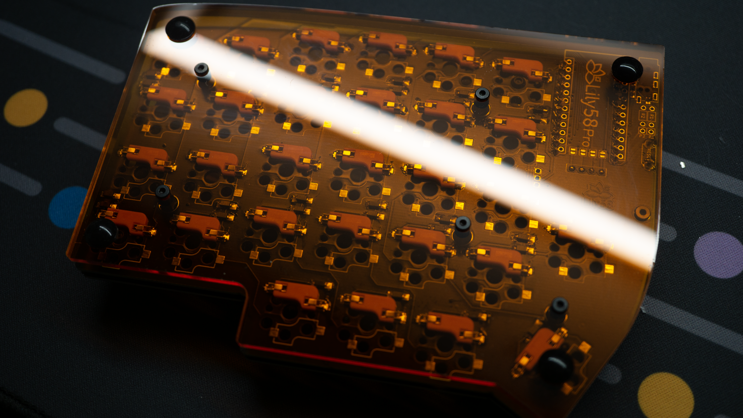
2 - Solder the SMD Diodes
We're going to solder the diodes on the DOWN side of the PCB so rotate your PCB in order to have the "UP" marker facing DOWNSIDE.
For an easier job, prepare one of the diode's pad with some solder
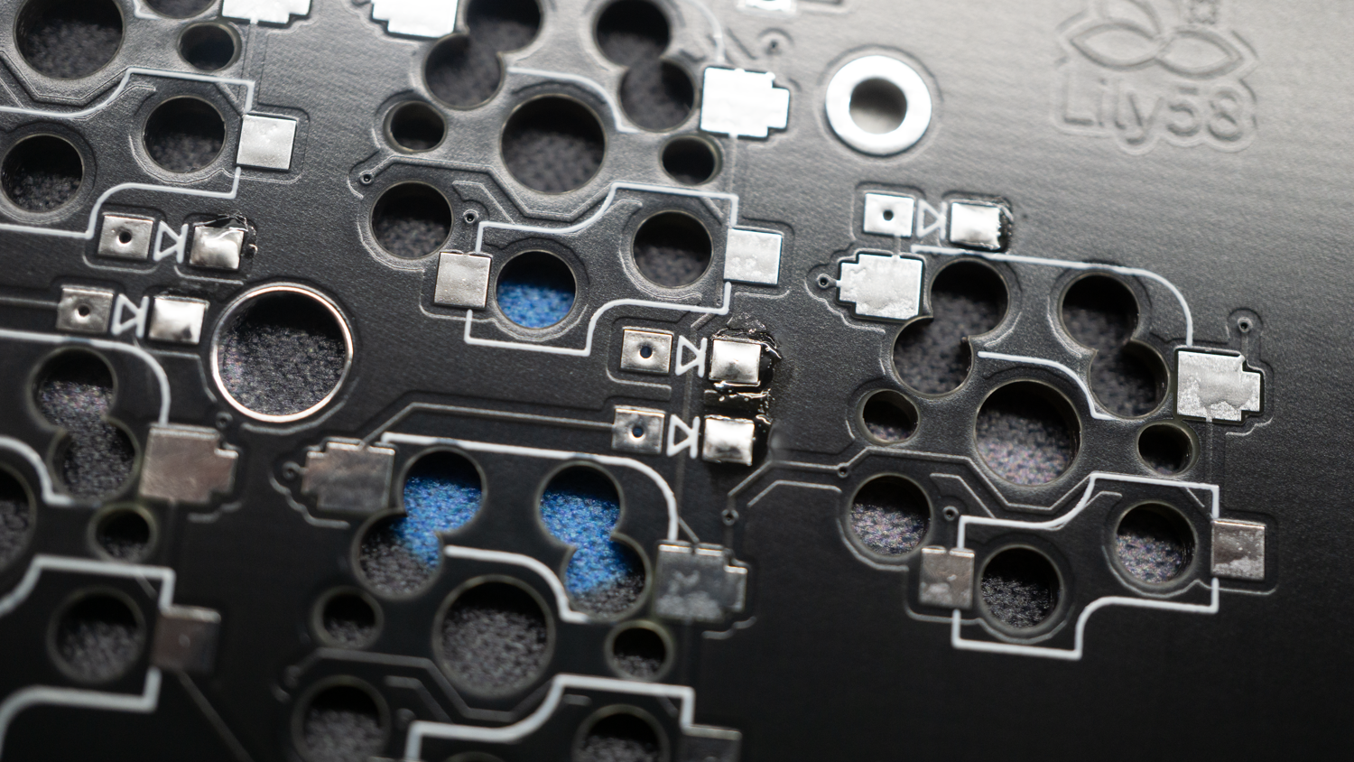
Position the diode with twizers on the right direction. The 3 stripes on the diode must be in the direction for the arrow drawn on the PCB.
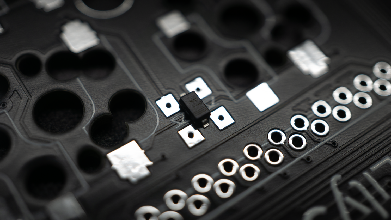
Hold the diode on the spot, heat the prepared solder pad until the diode is well soldered.
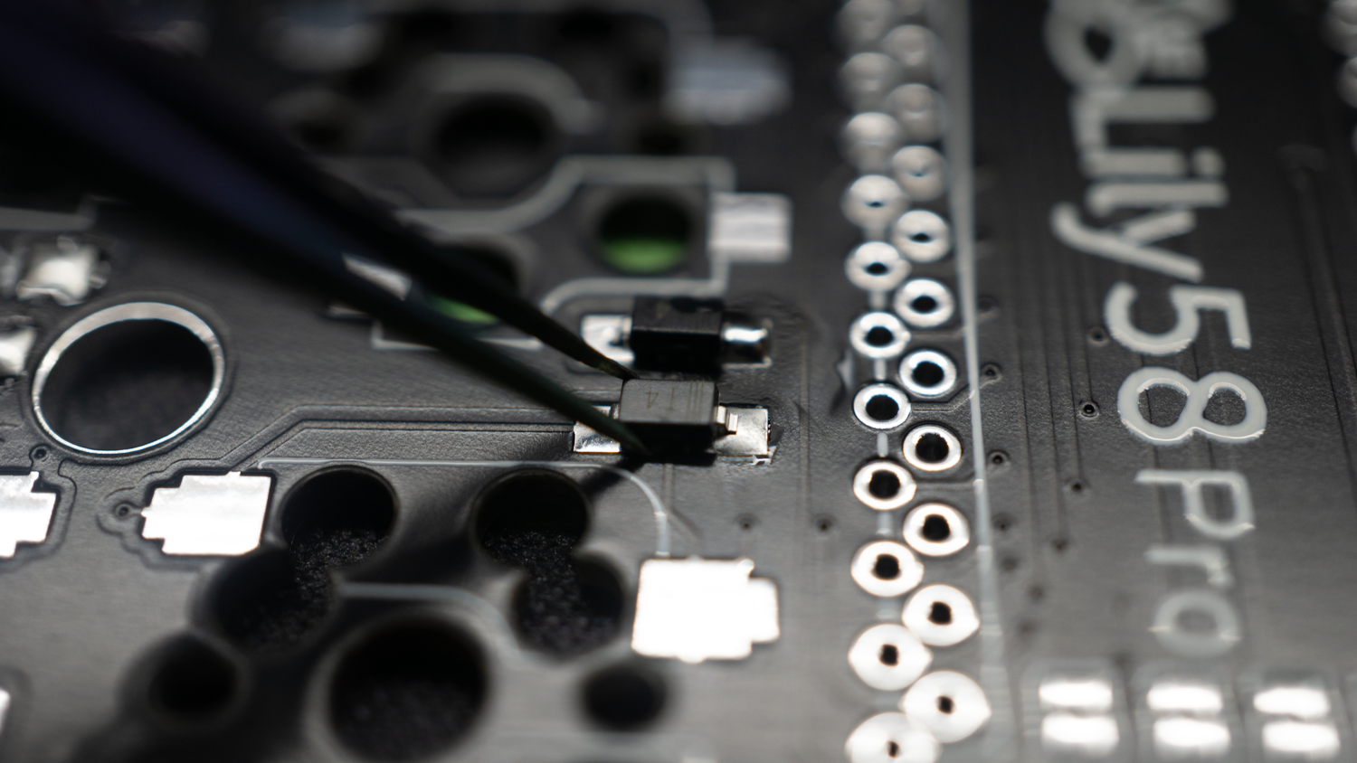
Repeat this step on all diodes.
After you've done with all diodes, solder the other the second pin of each diode.
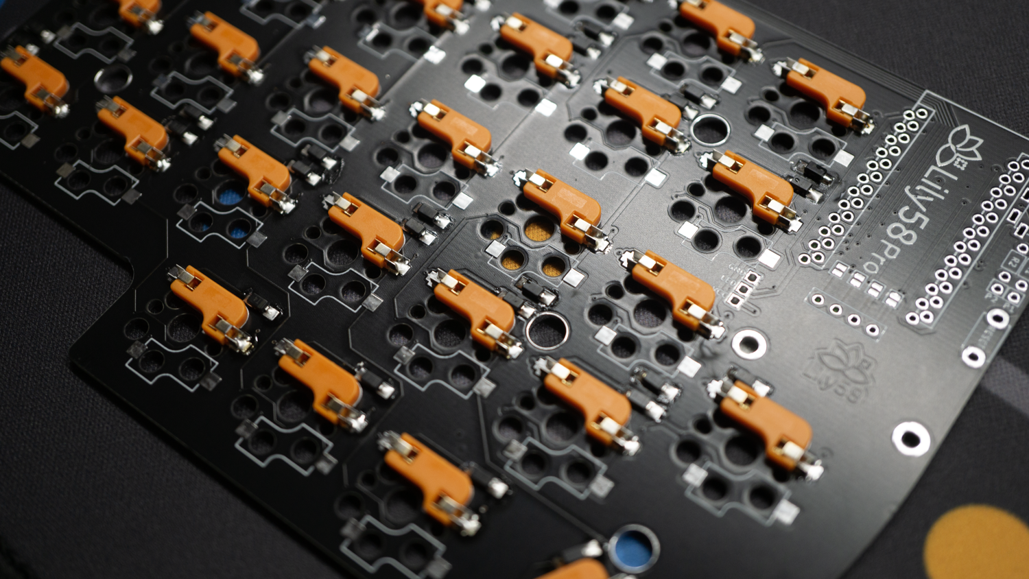
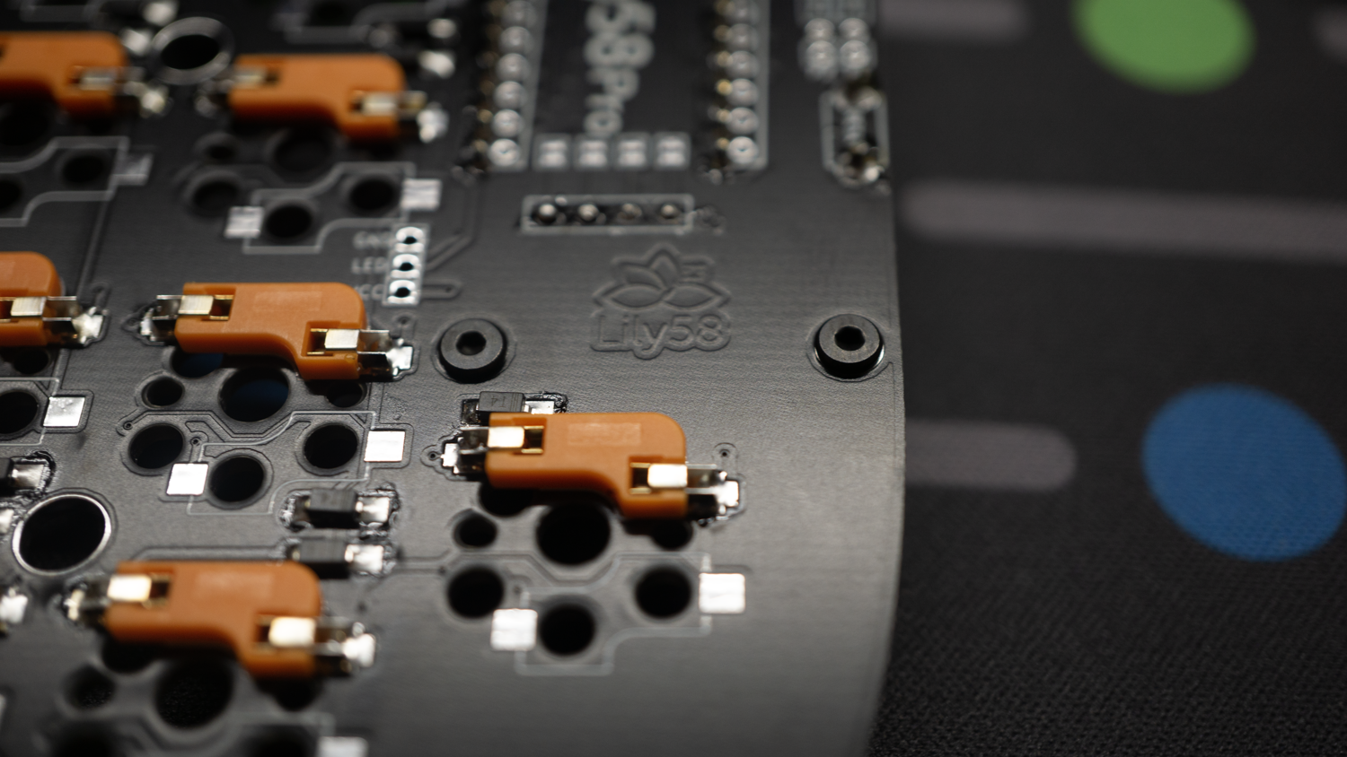
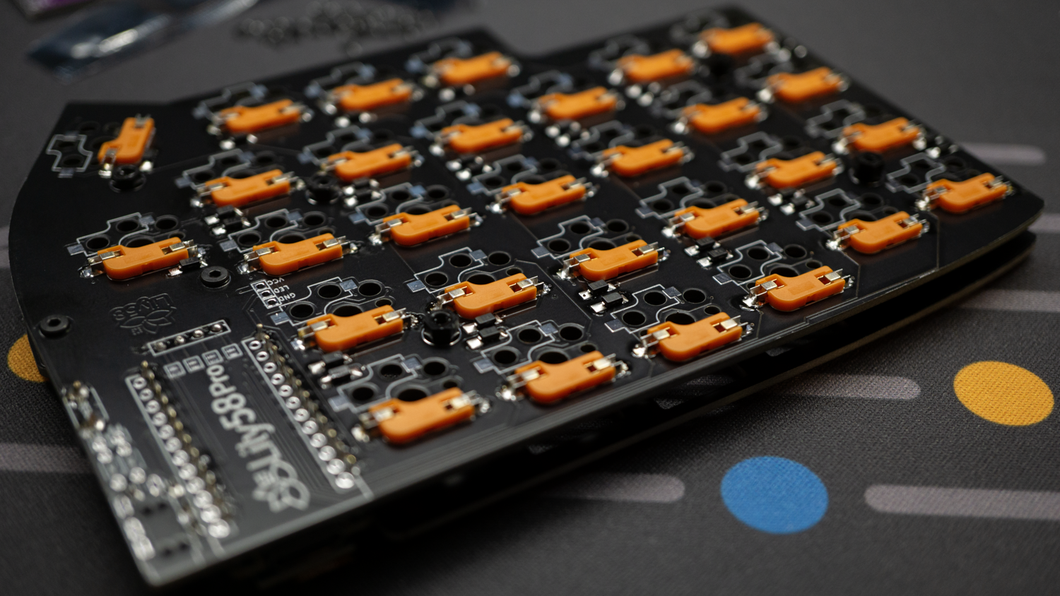
3 - Solder the Sockets
Position the socket in the same side as the diodes, solder process is the same as before, solder one pad for all of them and then solder the second one.
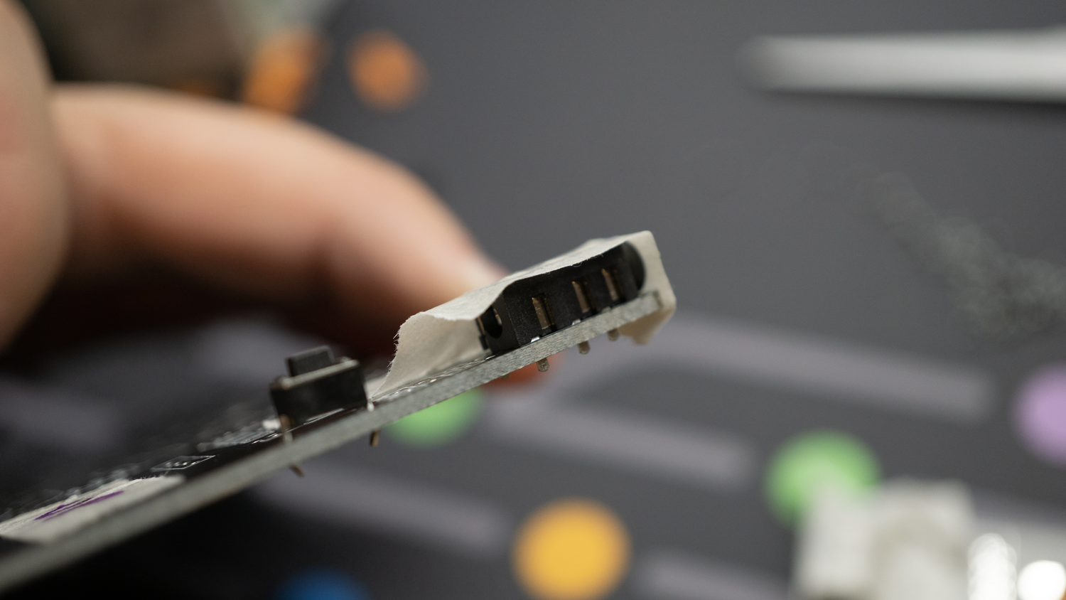
4 - Solder the TRRS and Reset buttons
Position, as shown, the TRRS and reset button on the UP side of the PCBs. Check the photo for the right pin position.
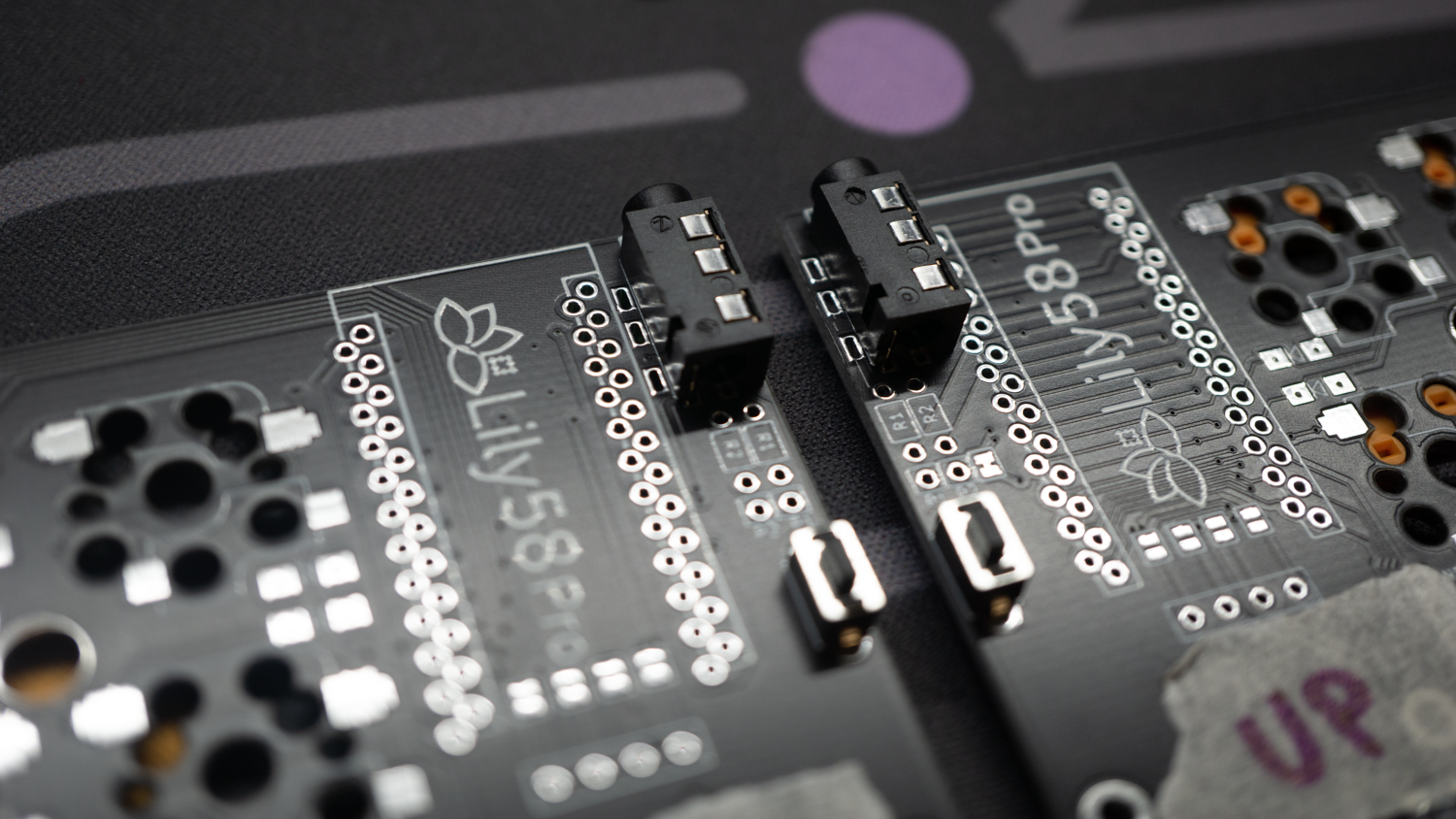
Use some tap to hold the TRRS and then solder them both.
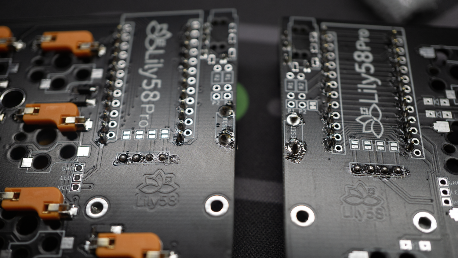
5 - Prepare OLED connection
Follow this step only if you're going to use an OLED display on your Lily58Pro.
With the two PBCs facing UP side, create a joint with some solder wire on the fow rails, by soldering them it will make a connection in order tomake the display work.
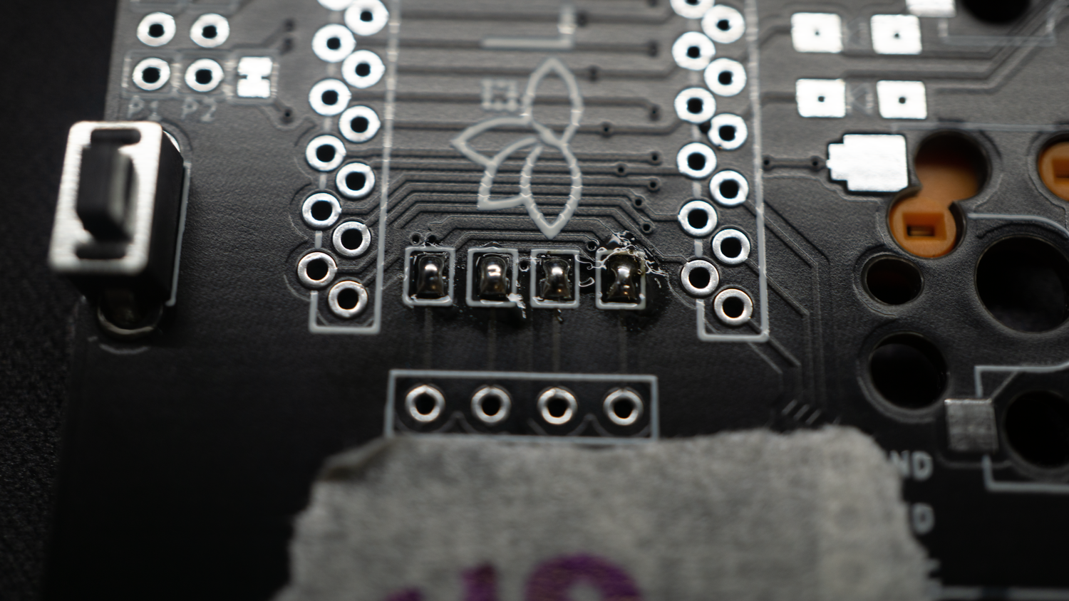
Do this step on BOTH PCBs!
6 - Solder your Microcontroller
Position the pin headers on the UP side of the PCBs, check the right holes as shown in the photo, all 4 strips must be inside the rectangle.
Now, after you soldered the pin headers, position yout Microcontroller on top of them, with the circuitery facing down.
The Position of the pins are different from the 32u4 to Helios RP2040, in the next photo both of them are shown, please position them as shown!!
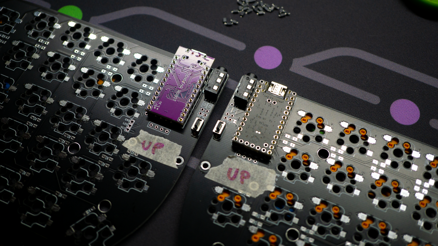
After the positioning is correct, solder all the pins to create a connection with the microcontrollers.
7 - Solder the OLED Display
Before soldering the Display, apply some electrical tape on the bottom of the display to cover sensible components that may short.
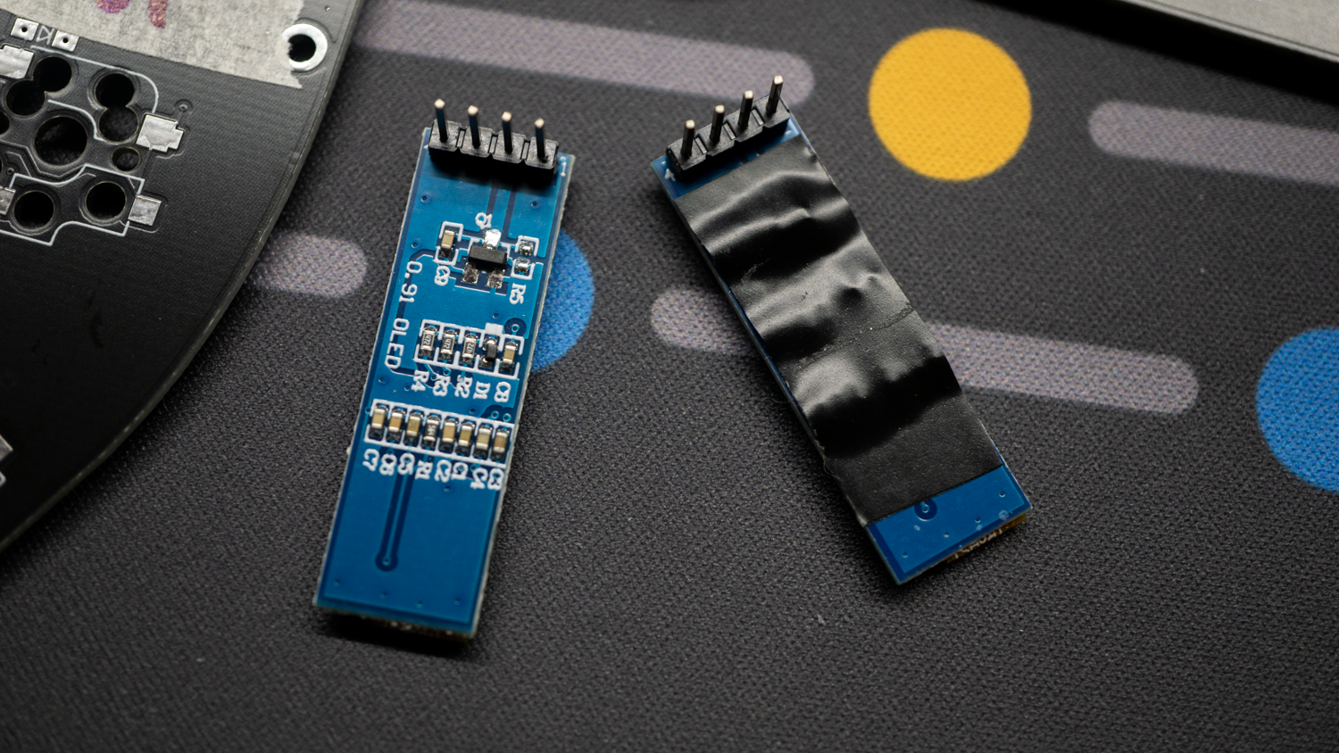
Insert the Display pins in the 4 holes by positioning the display on top of the Microcontrollers.
Now Solder the pins, they may be short but enough to be soldered as shown.
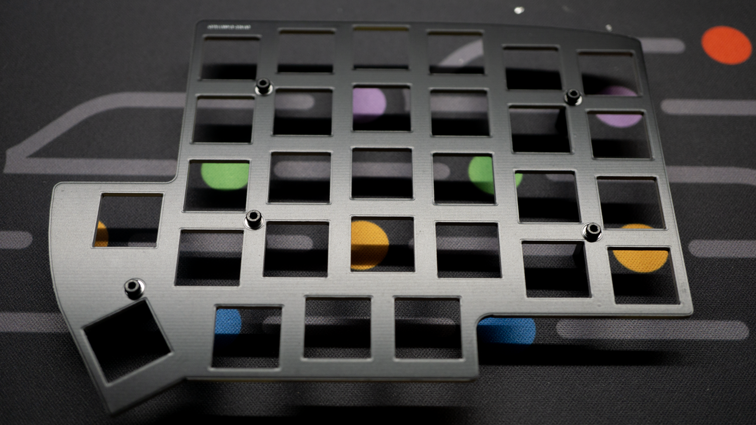
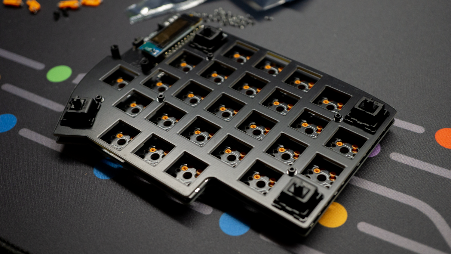
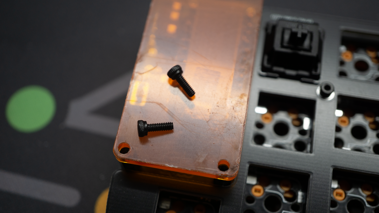
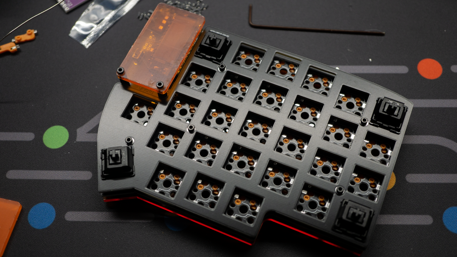
8 - Mount the Plate
Use M2 Cup Head 4mm screws to mount the 10mm standoff on the Plate.
Mount two other standoffs on the PCB, this thime facing UP side. Use M2 Flat head 4mm screws for those ones.
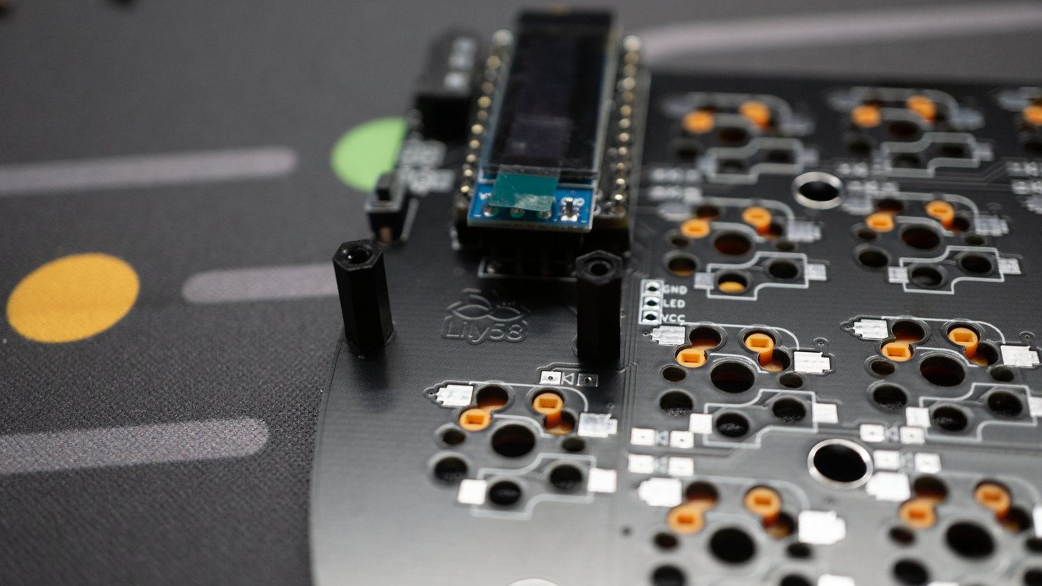
Now insert the Plates on the PCBs by fitting the standoffs in the PCBs' holes.
You can use some switches to let the plate and PCB stay in position on the right height.
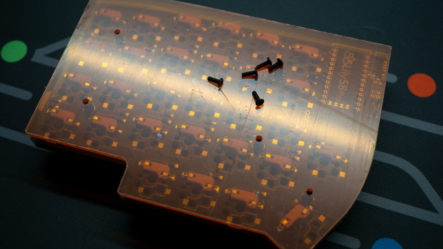
9 - Mount the Bottom
Depending on your model this step may be different.
9.1 - Standard FR4 Edition
With your standard FR4 Edition use M2 Flat Head 4mm screws to close your board.

9.2 - ZanniKB Edition (Or any Acrylic KIT)
With acrylic bottom layer use M2 Flat Head 6mm screws to close yout board.
10 - Apply rubber feet
If you have an acrylic version, remove the protection film before applying rubber feet.
11 - Mount the Display Cover
Use M2 Cup Head 6mm screw to mount the acrylic display covers. Remember to remove the protection films on both sides of the acrylic and also from the OLED display, after this stem is really hard to remove it without disassembly.
12 - Completition
Your board now is complete, add all switched and keycaps!
13 - Flash the firmware
This part depends on what Microcontroller you have. Download and follow the right firmware step!
13.1 Helios RP2040
With Helios RP2040 all you need is to download THIS file.
To flash the firmware on your board, connect ONE side of the keyboard at a time using USB-C cable. When connected, you will see a memory device called RP2040, open it and copy the UF2 file in the root folder. Your RP2040 should reboot automatically and if everything has been done right, you may see something on the display. Disconnect the board and repeat this step on the other one.
If you need to RESET and/or flash a new firmware, press reset on the board and follow the steps before with the new firmware
13.2 ATMega32u4
Whit this Microcontroller the steps are pretty standard as all 32u4 QMK based keyboards.
You will need THIS file for this Microcontroller. Connect ONE ONLY side of the board via USB-C and open QMK Toolbox. Press the reset button on the board, it'll reboot and a DFU device will be flagged on QMK Toolbox. Select the hex file you just downloaded and then click FLASH. Do not disconnect the board untill the process is done. Repeat those steps on the other half keyboard.
If you need to RESET and/or flash a new firmware, press reset on the board and follow the steps before with the new firmware
13.3 Other
Please follow the guide provided from the developer.
14 - Connect the board to your PC
In order to connect your board ALWAYS connect the TRRS cable to BOTH sides and then connect the USB-C to one of the boards. This Lily58 can also work with only one side connected, both will be detected as "left".
15 - Edit the Layout or keys
Both Firmwares for ATMega32u4 and Helios RP2040 are provided VIA Compatible so you can edit the default configuration of each key from VIA WEB.